Hi everyone and happy new year!
A couple of days ago (the new year's eve

) I had the frustrating experience of
bricking my MZD Connect CMU , getting a permanent black screen, while trying to update the firmware from v56.00.513 to v70.00.100, due to a failure during the failsafe step, because I left the Mazda AIO Tweaks installed before proceeding with the update.
I eventually managed to resurrect my CMU, to upgrade to the latest firmware and even (as a bonus) to install the retrofit kit for Apple CarPlay/Android Auto with complete success
, but it didn't come without some difficulties, especially to collect every piece of information needed to arrive to the final solution.
As many say on the web and throughout the forum unbricking a dead Mazda CMU it's a completely simple and doable DIY process, that can save you a bunch (1000~€), but at the same time it cannot be completely easy and straightforward when you know nothing of electronics, especially when it comes to buy some crappy cheap programming devices from the web where no accurate specification is given, and seldomly you manage to perfectly replicate the setup of a forum or a blog post.
For those of you that want to know every single detailed step-by-step information on how to resurrect a dead CMU, upgrade the firmware and how to install a retrofit kit, I will explain everything about my adventures here below.
1) Resurrecting a dead Mzd Connect CMU in case of failed failsafe installation:
CONTEXT:
The Mazda connect operating system is distributed on 2 chips:
- The failsafe is stored on a SPI NOR Flash memory of 8MB/64Mbit size, a Macronix MX25L6445E SOIC16 (16 total exposed pins) on the European version, but I heard of a Spansion chip on the US versions as well;
View attachment 285149
The failsafe name is really misleading, because the software loaded in this chip is actually the bios or if you prefer the bootloader of the CMU operating system, and this piece of software is crucial for the correct functionality of the headunit itself. Without it or with a corruption of its data, there is no way your CMU will boot anymore, and the screen will be black and dead.
This chip is located on the back of the CMU motherboard.
View attachment 285150
- The operating system (a sort of linux displaying html pages as GUI) is stored on a NAND flash located on the front of the CMU motherboard:
View attachment 285151
When we update the firmware of our CMUs
the main problems occur when we upgrade the failsafe image: this process involves, as you may understand, the reflash of the crucial SPI NOR flash memory... thus risking in case of failed installation, car shut down, corruption, or partial load to brick the CMU itself.... not so fail safe after all.
In fact the fail safe upgrade has been completely removed starting from firmware version v70.00.300+, I bet because they understood it was an uber risky process and finally decided to keep the "bios"/bootloader stable and untouched .... (they should have designed the system like this from the beginning, in a real fail safe way ...)
Credits for the mazda system teardown images:
Mazda Connect infotainment teardown
HOW TO FIX (without soldering for absolute beginners):
Now in the unfortunate case you bricked your CMU, what can you do?? Can you really resurrect your CMU even though you're not an expert or an electronic engineer?
Yes absolutely, but of course you should be careful and buy the right material. With an expense of maximum 50€ you will save yourself a 1000€ expense at the dealership.
Material:
- Trim removal kit: 10-20€ amazon link
This is needed to remove the car internal trims without breaking them, to get access and be able to remove the CMU from the car;
- 10 mm socket wrench
- a set of torx and cross screwdrivers
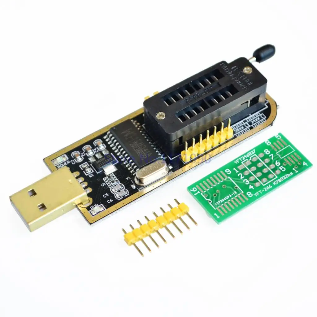
- 1x CH341A Programmer : 10-20€ / eu amazon link: ZHITING SOIC8 SOP8 Flash Chip IC Test Clips Socket Adapter Programmer BIOS + CH341A 24 25 Series EEPROM Flash BIOS USB Programmer Module (Doppia Clip + USB) : Amazon.it: Elettronica
A simple and super cheap SPI NOR flash/EEPROM programmer. This is the most important part: you absolutely need this to reprogram your CMU's MX25L6445E chip (SPI NOR flash).
View attachment 285152
NOTE: on Amazon there is a thousand of generic programmers available mainly coming from China.
You should keep one main concept in mind: the MX25L6445E is a 3.3v chip (datasheet, check page 8) and for this reason you ABSOLUTELY need a programmer that powers the chip's VCC with exactly 3.3v (most of the programmers would do that) otherwise you will fry your SPI chip.
Secondly (this is extremely important as well!!) the programmer that you buy should also program the chip with 3.3v tension; in other terms the logical channels (MISO, MOSI, etc.) should also be feeded with exactly 3.3v and NOT 5v otherwise the overvolted data channels will totally alter the data flow and you won't be able to read/write/verify valid data on the chip.
Moreover you risk to fry your chip also in this case (even though the risk is much lower since you're not directly over tensioning the chip power source).
View attachment 285153
Now this is very important to know.. most of the ch341a programmers that you will find online have an issue: they can feed the target chip in the socket with a selectable tension (using a jumper) of either 3.3v either 5v, but they will always provide a 5v tension to the logical channels... and this may be a big problem causing you big headaches as I explained you just above.
A successful programming may be impossible, or extremely hard, and moreover you risk your chip health.
At this point it's key testing with a voltage tester if your programmer feeds the chip and the data channels with a 5v or 3.3v tension.
Refer to these videos (ignore the soldering solution, just check which contacts voltage you should measure):
video 1 video2
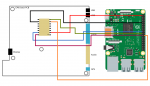
In case the channels are feeded with 5v, the solution resides in performing a simple volt mod on the programmer, to force the ch341a IC in a 100% 3.3v mode:
- Just cut with a cutter the PCB trace as visible in this picture (this will cut out the 5v incoming tension from the USB port, making the tension 0v on the socket itself):
View attachment 285154
- Place a jumper between the 3.3v and the 5v pins located on the usb programmer as in the following pic (this will bring the 3.3v tension back from the regulator and propagate it on the socket, reaching both the target chip's VCC and the logical channels, making only a 3.3v tension flow in the entire circuit):
View attachment 285156
Now we are ready to succesfully program our SPI NOR flash.
- 1x SOP16 IC Test clip with adapters ( amazon link ) or 8x single pin test clips ( amazon link ). 10-20€
Now this is the second crucial component: you need it to connect the programmer to your chip without desoldering.
If you decide to go for the 16pins test clip you want to make sure you will get in the package a SOP16 to SOP8 adapter as well. This will save you a big amount of time, because the wiring below will be already done.
View attachment 285158
If you decide to go for the 8x single pin test clips, or if you have no SOP16-SOP8 adapter provided with your SOP16 test clip, it's important to connect the 16pins of the MX25L6445E chip to the 8pins of the 25xx ZIF (zero insertion force) socket of the CH341A programmer correctly:
View attachment 285157
In this case the solution will be to manually connect each one of the 25 series socket's 8 pins to the corresponding pin of the MX25L6445E according to the schema above: to do this you can use jumper wires for your convenience or you can cut and rejoin clip cables. (example of manual connection performed cutting and joining cables)
- Jumper wires (always useful to make connections): 5-10€ amazon link
Software:
- CH341A programmer: this software is open source, you can search the internet for CH341A 1.18 programming software (check this how-to video description for a link to it), this is the best software to work with this SPI chip; otherwise you may try one between: AsProgrammer, NeoProgrammer or Colibri (also easy to find on Google);
- [optional] a non corrupted copy of your failsafe rom version (e.g: if before bricking it you had the 56.00.513 installed, you need a working version of the failsafe v56.00.513);
for v56.00.513 EU you may find it in the comments of this page: How I unbricked CMU in my Mazda
Procedure:
- Use the trim kit to remove all the trims and gain access to the CMU: you can refer to these videos to understand how to get access the CMU unit;
- Use the 10mm socket wrench to remove the main bolt holding the CMU, pull it and disconnect the connectors (be very careful, these connectors and matching pins are really weak, I managed easily to bend something and it was a nightmare make it fit again);
- Use the torx and cross screwdrivers to remove only the bottom metal bracket and case from the CMU so that you gain access to the CMU motherboard;
- Extract the CMU motherboard, put it upside down and get access to the SPI NOR flash chip, try to locate it using the above pictures as a reference;
- Clamp precisely the test clip on the MX25L6445E SPI chip so that the magenta cable (indicating PIN n°1) matches exactly the dot on the chip (indicating PIN n°1) (don't make mistakes: you won't damage the chip but without a good connection no programming will be possible);
- Connect the connector of the test clip to the SOP16-to-SOP8 adapter (making sure that the magenta colored wire corresponds to the silkscreened 1 on the adapter PCB) (otherwise perform the correct jumper connections as explained above);
- Place the adapter or the jumpers in the ZIF (zero insertion force) socket of the CH341A programmer (making sure you match the PIN n°1 of the adapter with the PIN n°1 of the 25xx side of the ZIF socket, that should be silkscreened on the programmer itself. In any case normally it's in the center right (4th pin of the right column from top) of the ZIF socket looking at it with the lever facing down. Check this how-to video to understand it better);
- NOTE: step 5, 6 and 7 are crucial: if you don't connect correctly the chip to the programmer no programming will be feasible;
- Install the CH341A parallel drivers on your PC
- Start the CH341A programmer on your PC, you should see a Device disconnected status
- Connect the USB programmer, you should see a Device connected status
- Click detect IC chip, the Macronix MX25L6445E should be detected (often is wrongly detected as MX25L6405D, this isn't a problem since the 2 chip have the exact same page size and total size);
- Click read chip;
- Click verify chip;
- If the verification is a success you can save the current status of the rom in a backup.bin file, to preserve your current status of the chip (even if it's broken you never know);
- Erase the chip and verify the blank space of the chip;
- Now you have two options: either you open the working ROM file of the same version of your CMU OS that I mentioned above (Software -> point 2), and program it to get your CMU working again (so for example you could then remove any existing tweaks and clean up your CMU before updating it), or in case you haven't found a valid rom for your CMU OS, you can just keep the corrupted version of the rom, go to hex offset 0x10000 (boot select partition) and change all the FF bytes of the row to 00 so that you change the boot mode from OS to update mode: this tells the CMU to start and try to complete the interrupted update. In this last scenario you will need to prepare an usb pen with the update you want to complete before mounting back the CMU in your car;
- Program the chosen ROM file on the chip and verify the correctness of the write;
- NOTE: Only if all of the above steps are passed with success you can proceed to reassemble the CMU with confidence that it will work;
- Re-assemble the CMU;
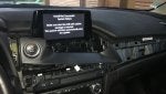
- Mount again the CMU in the car and in case you forced the update mode, complete the update procedure (make sure not to turn off the car this time);
Done! If you followed everything carefully you should, by now, have again a working & resurrected CMU
yay!
For a more clear overview of the steps I described, check out this extremely helpful
how-to video.
2) Updating firmware (without destroying) Mzd Connect CMU:
Find the correct firmware update for your CMU:
- if you have < 31.00.100 you should first update to v31.00.100
- if you have < 70.00.100 you should first update to v70.00.100
- if you have >= 70.00.100 you can update directly to v70.00.367 (latest)
I don't have links but you may find something on the internet.
Once you find your update copy failsafe.up and reinstall.up on a fat32 formatted empty <64gb USB pen.
EXTREMELY IMPORTANT NOTE: if you intend to update and you have Mazda AIO Tweaks installed on your CMU I strongly suggest you to remove all of them (perform system restore) before proceeding with the update, otherwise you risk to brick it for failure during failsafe installation (as it happened to me).
Also ensure that the usb pen contains only the update files and that is a fully working usb pen (any read error at failsafe installation time may end up into bricking your CMU).
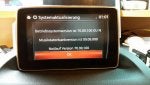
If you took all the above precautions you can proceed with the update. Follow carefully the PDF guide provided with the updates: before the update press 2 and 3 in the diagnostic menu and press the brake pedal every 10-20 minutes to avoid the CMU to shutdown in the middle of the update process.
Good luck!
3) [bonus] Retrofit CarPlay/Android Auto
This kit is really simple to install, just follow the video provided in the useful resources. You can find working compatible kits on Amazon for less than 150€. It just consists into a new more powerful USB HUB and cables (able to bring in more current, thus more data), and it makes the updated CMUs (at least on FW v70.00.021) enable the Android Auto and CarPlay features.
The kit you are searching for should contain cables
C922-V6-605A and USB HUB
TK78-66-9U0C and they should work for both EU and US versions of the CMU (according to forum sources, I can confirm for EU version:
link to working kit).
Useful resources:
I really hope that these information will come in a handy and be useful to anyone still facing these issues.
I thought it could be convenient to concentrate all these infos in one single page, since I spent couple of days collecting them all.
Finally I wish you again a happy new year and good luck with modifying your CMU!